Which screwdriver to disassemble macbook pro 13. How to disassemble a MacBook for cleaning or repair at home. Service center? No, I'm on my own
If this is your first time disassembling a laptop, we recommend that you pay attention to the article "". This article has recommendations that will help you avoid common mistakes during the disassembly process.
How to dust off a MacBook A1502
If the laptop overheats during operation and turns off abruptly, this is most likely due to overheating of the cooling system. The reason for this is the accumulation of dust on the radiator. If you do not clean the cooling system in time, this will lead to damage to the motherboard in the laptop. You can fix this problem yourself by repeating all the steps shown in the video below. The information provided in our video instructions makes it possible to clean the laptop from dust yourself at home. The necessary repair tools can be purchased at the end of the page.
Installing an SSD in a MacBook A1502 laptop how to change a hard drive
Video instruction on which you can independently replace HDD with SSD in MacBook A1502 laptop. You will also learn how to change a failed hard drive to a new HDD. Classic hard drives (HDDs) are more fragile and much slower than modern SSD drives. Therefore, replacing the HDD with an SSD will lead to an increase in the speed of the laptop at times. Our video below shows step by step instructions on how to install an SSD in a laptop.
Reassembly of the MacBook A1502
After completing the disassembly and repair, this video will help you reassemble the laptop to its original state.
With a 13-inch display, the de facto little brother of the 15-inch. It is noteworthy that this time the guys invited a special guest to the operating room - a kitten.
The patient himself, when closed, is difficult to distinguish from his older brother, and when open, by the missing speaker nets on the sides.
 Top - MacBook Pro Retina 13, bottom - MacBook Pro 13
 An exciting moment - the opening of the "hood"
 Doesn't it remind you of anything? Yes, this is Robot Number 5 from the movie "Short Circuit"!

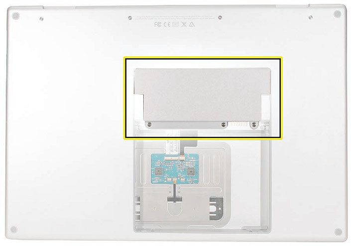
 Get the SSD.
 iFixit is surprised by this decision, because a full-fledged 2.5-inch SSD 5-7 mm thick can easily fit in the same place.
 As expected, the "bare" SSD is made by Koreans.
 Flash memory with a total capacity of 256 GB is marked yellow, and the purpose of the remaining details was not explained, but oh well.
 Next comes the Wi-Fi module with support for the AirPort protocol.
 By the way, the 15-inch "retina" MacBook Pro has exactly the same module.

 The holy of holies is the motherboard.
 Red - Intel Core i5-3210M dual-core processor at 2.5 GHz (Intel HD Graphics 4000 integrated graphics and auto overclocking up to 3.1 GHz), orange - Hynix 8 GB RAM, yellow - Intel QS77 chipset, turquoise - controller for the Thunderbolt interface.
 Orange is just the reverse of the RAM, purple is the Cirrus audio controller, the rest are unclear.
 This is what the MagSafe 2 power connector looks like.

 Wow! Six battery packs!
 Unlike the 15" battery, the 13" battery is much easier to remove.

Broadcom controller, same as iPhone 5. Interesting…
 Actually the touchpad.
 Summa summarum, maintainability score - 2 out of 10. Not the best result, but the big brother is even more a disgrace with his one point. iFixit has complaints about choosing a non-standard SSD, since it needs a separate cable. RAM is only 8 GB, with no choice of 16 GB version. The display is glued to the glass, and if during disassembly, God forbid, something breaks inside, then the entire expensive screen part can be sent to the trash.
A detailed guide for those who dare.
The life cycle of Apple laptops is significantly longer than that of competitors. It's hard to argue with this, especially when it comes to models released 3-4 years ago and earlier. A maximum of aluminum, well-thought-out ergonomics, the location of all elements - these are the devices that look at us from store shelves.

And somewhere in a parallel dimension, there are plastic heavyweights with controversial designs, creepy accessories, but a more loyal price tag.

Now the situation has leveled off. Brands competing with Apple have also learned to make beautiful things, and there are a number of parameters in which some laptop models even surpass the “reference MacBooks”.
But any technique sooner or later requires prevention. It's my turn to do the same.
Why did I decide
Note. I deliberately left the technical part of the question, terminology and aesthetics of service centers outside of this article. For any of us, results matter.
I have top 13 inch Macbook Air 2011. Five years ago, it was a “beast machine”, the processor of which (and here i7 1.8 GHz) grinds any load to smithereens. 4 GB RAM- then it was still a logical standard, and today it is enough for all everyday tasks.

The previous owner treated this “workhorse” with due trepidation, and for the last two years I have been exploiting it “to the tail and mane”. During this time, the MacBook was opened once, by me. After removing a layer of dust from the cooler area (we all like to work on our knees and soft pillows), the laptop was safely closed, but it didn’t last long.
Problem 1: Frying pan with an industrial fan
In my usual work mode, OS X has about a dozen different applications running, including: a text editor, Photoshop, the Safari browser interspersed with Opera (each with 10-15 tabs), mail, five instant messengers, iTunes, a couple of Finder windows. All this works relatively stably for the first half hour. And then the real hell begins.
The cooler spins up to the maximum (which is a good 6500 rpm), the keyboard warms up to a temperature that causes discomfort in operation. Applications begin to play with the matrix and react with an annoying delay ... It started to infuriate - it's impossible to work like that!
For the sake of practical interest, I install the application iStat Menus[Download] and with surprise I observe the following picture.

In the screenshot above, the temperature reaches 96 degrees. Let me remind you that at this moment I am not doing video editing or processing heavy files. At the moment of such a load, the temperature value crossed the mark in 105 degrees.
What is the risk? Too high a temperature can cause failure of any of the elements on the laptop board. The logical degradation of components begins: capacitors, resistors, crystals, and sooner or later you will simply face the premature death of the MacBook.
Repairing or replacing a motherboard is not cheap, so I strongly recommend periodically checking the temperature using the above utility.
Problem 2: I will tell you how to kill the battery
Working behind a large monitor is much more pleasant. It fits a lot of windows, you can effectively arrange the workspace, the realistic colors of a decent matrix delight (the era of CRT is already in the distant past) and your eyes are not so tired. Normal people buy Mac Mini or Mac Pro for this purpose. Our man - connects a laptop via Display / Thunderbolt Port, complements this with a proprietary Apple Keyboard and Magic Trackpad, and feels like a "winner in life."
To whom I refer, I think you already understood. 24 hours a day, the MacBook sits on my desktop, never turns off (thanks to its minimal power consumption), and is connected to the network adapter all this time.
After the purchase, my MacBook Air already boasted three hours of battery life. Six months of operation in the "system unit" mode and the battery life was reduced to 40 minutes, and the number charge cycles exceeded 650. You can see it in the menu About This Mac -> System Report -> Number of Recharge Cycles.

On the official website of Apple, the guarantee for preservation is indicated. 80% capacity after 1000 charge cycles, but, apparently, the company's engineers mean a more adequate operation option.
Detailed instructions for those who dare.
Do not repeat my mistakes and treat your Mac battery with care. How to do this I will tell below.
What is the risk? You feel constantly tied to the outlet, and the question: “Do you have a laptop” is simply difficult to answer.
Verdict. It's decided - it's time for general prevention. The first item on the list is cpu thermal paste replacement with all the resulting dust eliminations. Second - battery replacement.
Service center? No, I'm on my own
The computer services industry is well developed today. One call and a representative of the service center will come for your Mac, pick it up himself, then within a day they will do a “full maintenance” and deliver it back. There are a lot of scenario options here and you can always find a company or specialist who will make your MacBook “like new”. The question is, how good is it?

Yes, many do just that - they took it to the center and let them figure it out. I, as a person who is interested in technology, technology, and especially everything related to Apple, became interested in do it all on your own.
My readers will now be divided into two groups: those who say: “Yes, what is the heroism here - an hour of work and everything is ready” and those who twist at the temple with the words: “Well, come on, you’ll still do it crookedly. We need a specialist in this matter." I think there is a third category that will support my desire to climb where it is not supposed to.
Buying a battery and thermal paste
So I need new battery for MacBook Air 13'' 2011 and thermal paste. In addition to rumors and beliefs that fakes are everywhere, and the original does not exist (and there is some truth in this), I have nothing to present to the market in the battery issue. With thermal paste, everything is solved easier and according to the principle “so help me forums”.
The first and most important thing is to find out which battery model installed specifically in your MacBook. Information can be easily found on the Internet, indicating the exact model name and year of manufacture (do not forget about the screen size), but it is best to see the required serial number with your own eyes.
In order to open the MacBook, we need a non-standard (for other household appliances) screwdriver format Torx T5 or "asterisk".

Ideally, you need to have two screwdrivers at once: T5 to open the laptop lid and T4 to remove the internal screws that hold the battery, cooler, and heatsink in place. So the fixing screws will not experience wear from an unsuitable screwdriver format.
Using a T5 screwdriver, carefully remove the 10 screws:

The two center top screws are longer than the other 8 - remember this when reassembling.
Now we define the battery model.

The 2011 MacBook Air 13'' has a battery number A1405. And then it's a matter of technology - look for the most suitable store on the Internet and order the model you need. Finding "100% original" is more like a myth, so take the Chinese markings and characters on the battery calmly. In the end, and your MacBook proudly bears the inscription on the back of the case: Made in China.
Regarding the thermal paste. There are many good options on the market:
- Glacial Stars Ice Therm I
- Arctic Cooling MX–2
- DEEPCOOL Z3
- Arctic Silver Ceramique 2
- CoolerMaster IC Essential E1
- KPT-8 in the end - it is quite good
If you wish, you can do a detailed analysis of the effectiveness of each of the above pastes. Personally, I didn’t have time for a thorough study - the work stopped, and the open Mac was waiting for the operation.
My choice fell on CoolerMaster IC Essential E1 for several reasons at once. Firstly, it is a little cheaper than the hyped Zalman, and secondly, according to numerous reviews, it does an excellent job of cooling.

Finally, you buy a complete set for laying the paste yourself: the tube itself with the “saving substance”, an alcohol wipe and a spatula for leveling the paste layer on the processor. The issue price is about 600 rubles, but the volume of the tube is enough for a dozen or two processors.
We change the battery
Everything you need for prevention is on hand. Torx T4/T5 screwdriver, new battery, thermal paste, hands and full focus.

The only thing that is not in the photo is a wooden stick or toothpick to turn off the trains. In no case do not use a metal screwdriver for this.
Immediately before starting work disconnect the cable leading to the battery.

We unscrew the screws around the perimeter of the battery. Do not be too lazy to take an A4 sheet and schematically sketch the location of each screw. They have different lengths and threads, and when reassembling there is a risk of screwing something in the wrong place, thereby piercing the body of the device.
I did like this:

For disassembly, you need to unscrew exactly five screws, using a Torx T4 screwdriver.


When removing the battery, be extremely careful and try to hold it from all sides at once. The battery may break under its own weight.
The original and the newly acquired "100% original" are no different from each other.


The only thing that catches your eye is the absence of a plastic tail for extraction on the purchased battery.

It's not critical, we'll survive.
We install a new battery in place and fix it with screws, according to our scheme. Each screw has its place. Try not to apply force, a moderate turn of the screwdriver is enough.
After installing the battery loop is not connected, because ahead is the most time-consuming part of the prevention - the replacement of thermal paste.
Change thermal paste
Using a toothpick, carefully pry off the ribbon cable located above the cooler. It is glued to the body of the cooler, so it will take a little effort to tear it off.

Again, use a toothpick to turn off the miniature cooler cable by gently lifting the tab and pulling it out.

Now, using the same Torx T4 screwdriver, unscrew the three screws holding the cooler and carefully remove it.

We proceed to the removal of the radiator. There are already four screws waiting for us. Try to remember the effort that you had to make to break them - when reassembling, you will need to tighten the screws in the same way.

After you unscrew the 4 screws, do not remove the radiator. It is fixed in one more and very problematic part.
Near the cooler, in the very corner, there is dangerous area- a miniature wiring, under which there is a screw fixing the cooler.

Carefully move the wire aside and remove the screw. The main thing is not to damage anything. Remove the radiator by loosening from side to side and releasing the rubber seal.
While unscrewing the screws, make another schematic drawing with their location. It is important! The screws are different.

Using a can of compressed air or a syringe, get rid of the dust that has formed on the radiator grill. Of course, the same should be done with the cooler.
Access to the processor chip is guaranteed!
Yes, what was left of the factory thermal paste could not save the MacBook from overheating. It has dried out and does not provide proper thermal dissipation.


Using a cotton pad and alcohol, carefully wipe the processor (to a mirror finish) and the heatsink.

We have come to the most crucial moment - applying thermal paste. Faced with the self-replacement of the paste, many users are faced with the problem: what is the optimal amount of thermal paste to apply?
In order to understand why thermal paste is needed at all, look at this picture:

The purpose of replacing thermal paste is to provide smoothing and filling of microcracks on the surface of the processor and heatsink. She is not needed to be a layer between them. Therefore, with the approach: “I’ll put more - I’ll cool better” you will only make it worse. The thermal paste will dry out very quickly and cease to perform its function, losing the necessary physical properties.
You need to distribute the paste in a thin layer over the entire surface of the processor. Approximately this amount:

Then, using a spatula, level the thermal paste.


When everything is ready, do not rush to immediately apply the radiator. Try on its location and pay special attention to the rubber seal. It should fit into the motherboard slot.

Only then can you properly install the radiator. Be careful when screwing in the corner screw (where the dangerous wire is). Don't overtighten the screws, do it gradually on each side.
When installing the battery, make sure that the barely visible slot on the plug snaps into place.

We close the back metal cover, tighten ten screws around the perimeter.
Assembly completed!
The effect of replacing thermal paste, battery and some tips
Having done everything that I described above, I independently performed the preventive maintenance of my beloved MacBook Air. But the question that worried me even before starting all this was the effectiveness of the event.
I'm telling.
Thermal paste. Before replacing the thermal paste, the temperature of the laptop rarely dropped below 95-100 degrees. The cooler worked at full capacity even when applications were not running, and the temperature to which the case heated up made it impossible to work.
You type text in the editor - 92-94 degrees, launch Safari - all the same. You open Final Cut - the mark of 105 degrees submits. The cooler works, but there is no sense from it. He didn't chill!
Replacing the thermal paste and cleaning the cooler worked magically. He stopped making noise! When you run heavy applications, the MacBook instantly heats up, the cooler slowly spins up and falls within a minute. And the temperatures now look like this:
- Working in Final Cut Pro X (video editing) - 94-97 degrees
- Surfing, music, instant messengers, Photoshop - 70-80 degrees
- Work in text editor- 40-45 degrees.
The temperature in the room is a hot summer day, about 23-25 degrees.

I have NEVER seen the last figure on my MacBook Air. Working in complete silence is a real pleasure. Nothing distracts you, does not pester and does not annoy. Was the game worth the candle? Definitely!
Battery. 40 minutes is the maximum I could afford without an outlet. After switching on, the new battery was 52% charged. We all have heard about the calibration, which is associated with constant disputes and speculation.
Battery calibration IS NEEDED. Of course, if you are interested in her adequate further work. What I did after the first inclusion:
- Immediately connected the power adapter and charged the battery to 100%
- Discharged to 10% and re-charged to 100%
- Repeated the cycle 3 times
That's all, that's enough. Don't be surprised if the program iStat Menu will constantly show different battery capacity and health values. This is normal until the battery is pumped, which may take about 20-25 discharge / charge cycles.
When using the battery, try to work in the 20-100% mode. Don't let your battery drain completely, and stop working after your Mac prompts you to critical charge. Try to take your MacBook off immediately after it is 100% charged. So you can not worry about battery life and battery degradation for several years.
Of course, this is just a recommendation. Modern batteries (and even more so from Apple) are equipped with the necessary protection controllers and provide maximum service life without unnecessary “dancing with a tambourine”. Apple technology is designed for comfort, and it's up to you to follow the operating tips or not.

At the time of finishing this article, my Mac promises to work for another 4 hours and 15 minutes. The number of full charge cycles is 7. The temperature indicator is 46 degrees (I work on my knees). The cooler rotates at a minimum of 2000 rpm, but it seems that it does not work at all.
(4.75 out of 5 rated: 4 )
![]()
General Information
product view
Overview
The MacBook Pro (15-inch Core 2 Duo) is the next generation of Intel-based MacBook Pro
professional notebooks. As the name implies, it is based upon the new Intel Core 2 Duo chip,
increasing processor speeds up to 2.33GHz.
On the exterior, the MacBook Pro (15-inch Core 2 Duo) difers from its predecessor in two ways.
The LED for the iSight camera no longer depends an opening in the display bezel to be visible.
And more signifcantly, the reintroduction of FireWire 800 adds a new port to the right side of the
bottom case, increasing the ports from four to fve.
A new MagSafe Airline Adapter is now available for both the MacBook Pro and the MacBook. Plug
the MagSafe Airline Adapter into the EmPower port nearest your airline seat. Some airlines may
have 20 mm in-seat ports that require the use of an additional adapter (included in the kit).
Main service and feature differences from previous models:
- Intel Core 2 Duo microprocessor architecture: 2.33GHz and a 2.16GHz option
- Up to 3GB DDR2 memory now supported
- 120GB 5400 RPM hard drive standard
- 100GB 7200RPM hard drive optional
- 200GB 4200RPM hard drive optional
- FireWire 800 port
- 6x SuperDrive with dual-layer burning support
- New trackpad-enabled zooming feature
New Parts and Procedures
Main Logic Board
The MacBook Pro (15-inch Core 2 Duo) not only hosts the Intel Core 2 Duo microprocessor chip,
but it also reincorporates the popular 9-pin FireWire 800 port from the PowerBook series. note
that the additional port makes this bottom case incompatible with previous the MacBook Pro.

Like the MacBook, the MacBook Pro (Core 2 Duo) now utilizes JST wire bundle connectors that
disengage by lifting up and pulling the connector out of its mating part on the logic board. Just
snap the connector back in. The fans, thermal sensors, and back battery all use this connector.

As with its predecessor, the composite and S-video connection is still available using the optional
Apple DVI to Video adapter. The microprocessor is soldered to the main logic board. It is not
upgradeable.
Memory
The maximum supported amount of memory is 3 GB. While you will have a perfectly bootable
system with two (2) 2GB RAM modules installed—and even About This Mac will report 4GB of
installed memory—the system will only be able to address 3GB of that installed RAM.
AirPort Extreme
The AirPort Extreme card is a new design that utilizes a three-wire antenna solution. A color-
coded label will identify which wires go to which terminals on the card.

Bluetooth
The Bluetooth module and antenna have been moved from the bottom case near the hard drive
to a position underneath the top case.
iSight Camera Status LED
The opening for the green status LED to the right of the camera no longer appears in the display
bezel. When the LED lights up, it is now visible through a clever pattern of micro perforations.

Keyboard
The keyboard backlighting has been improved. In addition, the programming of the caps lock
key was changed to fx a developer keyboard mapping issue. Thus, this keyboard cannot be used
in previous MacBook Pro 15-inch systems. The caps lock key will not be recognized.
Right Speaker Assembly
The right speaker is now one single part. In the previous design, a speaker housing was mounted
below the main logic board and the right speaker driver was mounted through the main logic
board into the housing with its wire running over the top of the main logic board.
The new single piece design has the entire right speaker installed frst with the main logic board
placed over it. This design does require the entire main logic board to be removed to change the
right speaker. In addition, the right speaker wire now runs below the main logic board, under the
heat sink along back vent wall.
Trackpad
The trackpad now supports screen zooming, much like the keyboard-based Zoom feature in the
Universal Access System Preference pane. When holding down a user-selectable modifer key (in
the Keyboard & Mouse System Preference pane), gesturing with a forward fnger motion on the
trackpad will cause the image on the screen to zoom in. The reverse motion will zoom out.

There are three users options that adjust how the customer can move within a zoomed screen
and how smooth the image will look.

hard drive
The hard drive comes with a metal disk attached to its top cover to dampen hard drive noise. This
disk is not removable. The replacement drive will come with this dampener pre-installed.
Temperature Concerns
The customer may perceive this system to run hotter than previous models. However, the normal
operating temperature is well within national and international safety standards. Still, customers
may be concerned about the heat generated by their machine. To prevent an unnecessary repair
you can compare a customer's computer to a running model, if available, at your repair site.
For more information on temperature concerns and customer perception, refer to Knowledge
Base article 30612: Apple Notebooks: Operating Temperature.
Display Takeapart
With the MacBook Pro (15-inch Core 2 Duo), we have brought back the whole display clamshell
as a service part. However, unlike the 17-inch Core 2 Duo, we offer some parts which are
accessible by the removal of the display rear housing.
Specifically, a Service Provider can replace:
Display hooks
. inverter
. display housing
. Sleep magnet
All other parts including the LVDS cable are serviced with the whole clamshell module.
Identifying the MacBook Pro (15-inch Core 2 Duo)
Below are views of the MacBook Pro (15-inch Core 2 Duo), with identifying features.
Left side: MagSafe™ magnetic power connector.

Right side: New FireWire 800 port.

Front: Infrared sensor window.
Rear: Wider venting than previous MacBook Pro.
Display bezel: MacBook Pro.
Serial Number and Ethernet ID
The Serial Number and Ethernet ID are located in the battery bay.

The takeapart procedure for the MacBook Pro (15-inch Core 2 Duo) requires the following tool
- ESD wrist strap and mat
- #1 Phillips screwdriver (magnetized)
- 4mm socket wrench
- Black stick (nylon probe 922-5065) or other non-conductive nylon or plastic fat-blade too
- Razor knife
- Needle point metal probe
- Needlenose pliers
- Tweezers
- Thermal Grease (922-7144)
- Gasket kit (076-1238)
- Alcohol pads
- Apple Pro keyboard and mouse (for troubleshooting)
Electrostatic Discharge (ESD)
Use a properly grounded ESD wrist strap and mat when working on the inside of the computer.
Service Manual Note
In this manual, graphics or photos are intended to help illustrate procedures or information only,
and may show diferent levels of disassembly, board colors, confgurations, or computer models,
than your computer.
Kapton® Tape Note
Kapton tape is used to secure cables and connectors where necessary.
During disassembly, note any Kapton tape use and locations—reapply in the same manner. Do
not over apply or build up tape on top of old tape; space tolerances are tight and build up or
extraneous use of tape may cause pressure on other components.
Cable Routing Note
The MacBook Pro matches the same one-inch enclosure height established with the PowerBook
G4 17-inch series of systems. More so than ever, the placement of parts and wiring is critical.
During disassembly, note cable routing. Reassemble in the same manner. Verify that cables do
not route over components when they should route into lower positions or channels. Verify that
the cables are not strained or applying pressure onto other components.
Screw Measurement Note
All screw measurements given are the specified full length. Actual measured lengths may vary.
Foot
- foot kit
- Tweezers or needlenose pliers
- softcloth
Preliminary Step
Before you begin, check the foot location that needs replacement and verify that the case plug is
attached. Also verify that the case plug, and the case foot in the kit, match the pictures below.

procedure
Warning: The glue used in this procedure can bond instantly to skin. Do not touch the glue.
In the event of contact, review the safety instructions at the end of this document. For
additional information, refer to the glue manufacturer:
Elmer's Products Inc.
Columbus, Oh. 43215-3799
www.krazyglue.com
1.Place the computer upside down on a clean, lint-free cloth or other nonabrasive surface.
2.Select a foot from the kit. Verify that the case plug and case foot match (refer to the images
shown in the table). Do not use a foot that does not match.
3.Make sure the plug area on the bottom case is clean. If any portion of the soft rubber foot
remains, remove it so that only the hard plastic plug is visible.
Important: When positioning the foot, make sure the indents and bumps of the rubber foot
match up and ft into the corresponding indents and bumps in the plug. This ensures a
balanced and level ftting. (Note: The picture below may be a different foot than on the
computer, and is for illustration only.)

4. Warning: GLUE IS AN EYE AND SKIN IRRITANT. BONDS SKIN INSTANTLY. Don't touch the
glue at any time. Before opening the glue, review the safety instructions at the end of
this document.
Important: The glue tube included in the kit is sealed until frst use. Do not break the seal
until you are ready to use the glue. To break the seal, hold the tube up right and away from
you. Place the hollow nozzle cap on the tube and tighten it all the way down. The tube is
then ready to dispense the glue through the nozzle cap.

5.Apply one drop of glue to the plug on the bottom case. Do not spread the glue.
6.Using tweezers or needlenose pliers, carefully position the new foot so its textured surface
fts into the inner ring of the plug.
7.Using the end of the tweezers or pliers—not your fnger—lightly press and hold the foot in
place for 30 seconds.

2.Before turning over the computer, allow the glue to set for at least 15 minutes.
3.Discard the tube of glue.
SAFETY INSTRUCTIONS: GLUE IS AN EYE AND SKIN IRRITANT. BONDS SKIN
INSTANTLY. Contains ethyl cyanoacrylate. Avoid contact with skin and eyes. if eye or mouth
contact occurs, hold eyelid or mouth open and rinse thoroughly but gently with water only for 15
minutes and GET MEDICAL ATTENTION. Liquid glue will sting eye temporarily. solidified glue
may irritate eye like a grain of sand and should be treated by an eye doctor. If skin bonding occurs,
soak in acetone-based nail polish remover or warm soapy water and carefully peel or roll skin
apart (do not pull). Contact through clothing may cause skin burn. If spilled on clothing, fush with
cold water. Avoid breathing of vapors. Use with adequate ventilation. KEEP OUT OF
REACH OF CHILDREN.
Battery
Tools
Clean non-marring work surface
Preliminary Steps
Warning: Always shut down the computer before opening it to avoid damaging its internal
components or causing injury. After you shut down the computer, the internal components
can be very hot. Let the computer cool down before continuing.
Part Location

performing this procedure.
- Shut down the computer.
- Disconnect the power cord and any other cables connected to the computer.
- Place the computer face down.
- Slide both battery latches away and lift the battery out of the battery bay.

Memory
Tools
This procedure requires the following tools:
- #0 Phillips screwdriver (magnetized)
- Clean non-marring work surface
- ESD wrist strap and mat
Preliminary Steps
Battery
Part Location
Warning: If the computer has been recently operating, allow it to cool down before
performing this procedure.
1.Place the computer face down.
2.Remove the three screws from the memory door.

3.Remove the door as shown.

Notes:
. If only one memory card is installed, the factory installs it in the bottom memory slot.
. Memory must be removed from the top slot before removing from the bottom slot.
4.To remove memory cards, carefully spread the two locking tabs for the slot (top or bottom)
away from the card on both sides and allow the card to pop up slightly.

5.Pull the card straight back and out of the memory slot. Handle the memory card by the
edges only, taking care not to touch the gold contacts.

Replacement Procedure
- DDR memory cards do not ft in this slot, only DDR2 (different notch location).
- If installing two cards, install into the bottom slot frst.
- Align the notch in the memory card with the tooth in the slot before inserting.
1.To install a memory card into either the top or bottom slot, insert the card at a 25-degree
angle behind the locking tabs.

2. Firmly push the card straight into the slot until it is fully and securely seated along its length.
Note: If the back of the card drops down before it is fully seated, raise it up enough to push
it fully into the slot.
3.When the card is fully seated, push the card straight down until the tabs click onto both
sides of the card, locking it into place.

4.Verify that the card is fully seated by pushing frmly with your thumbs.

5.Check that the cards are secured by the brackets on both sides.
6.Install the memory door.
7.Replace the battery.
8.Use Apple System Profiler to verify that the memory is recognized. (Choose the menu
bar Apple logo > About This Mac, click More Info..., select the System Profile tab,
open the Memory Overview.)
NOTE: As mentioned in the General Information section of this manual, the maximum supported
amount of memory in the MacBook Pro (15-inch Core 2 Duo) is 3 GB. While you will have a
perfectly bootable system with two (2) 2GB RAM modules installed—and even About This
Mac will report 4GB of installed memory—the system will only be able to address 3GB of that
installed RAM.
Top Case
This procedure requires the following tools:
- #0 Phillips screwdriver (magnetized)
- Torx T6 screwdriver (magnetized)
- Multi-compartment screw tray (such as a plastic ice cube tray)
Preliminary Steps
Before you begin, remove the following:
- Battery
- memory door
Part Location

procedure
- If replacing the top case, once the top case is removed, use a razor knife to carefully lift and
transfer the Serial Number and Ethernet ID labels to the replacement top case.
- This procedure removes the top case and keyboard assembly. The keyboard is removable
only after removing the top case.
1.Place the computer upside down on a soft, non-marring surface.
2.Remove the four Phillips and two Torx T6 screws shown.

3.Rotate the computer and remove the two Phillips screws along the front of the battery bay.

4.Remove the four Phillips screws from each side.


5.Remove the two Phillips screws from the back edge.
6.Face the computer forward and open the display slightly past 90-degrees.
7.Use a black stick to loosen the top case along the rear of the left and right sides.


8.Along the front, start at the left and slowly encourage the snaps and screw tabs (shown in
graphic below) to release as you move right. A snapping noise as the snaps release is normal.


Important: Do not lift the case once it is free—it is still connected to the bottom case by the
keyboard fex cable.
9.Important: To avoid bending screw tabs along the back edge of the top case, lift the top
case so slightly that it does NOT touch the bottom case, then rotate the front of the case up
and back until you can disconnect the keyboard fex cable from the logic board.


Replacement Procedure
Note: If replacing the top case, remove the keyboard and transfer to the replacement top case.
1.Visually check to verify that all cables are connected and routed correctly with nothing raised
up or incorrectly over a component.
2.Check perimeter wiring and cables around clutches to verify that they will not be caught or
pinched by the top case during replacement.
3.On the computer, verify that all cables are secure and lay fat.
4.On the top case, check cable connections and routing.

5.Check that the perimeter screw tabs and ribs are not bent.
Note: The metal can quickly fatigue and break of. Be extremely careful to gently straighten
tabs, if needed.
6. Verify that the plastic spacer is on the front screw tab, shown.

7. Verify that the screw tabs in back are straight and guide them inside the bottom case. Work
your way around guiding the screw tabs into the bottom case along both sides.

8.If the back screw tabs are bent out, straighten by pressing the edge of the case on a hard fat
surface and rolling to vertical.

9.Any screw tabs that are not straight will not ft or accept screws correctly.

10.Use your fnger and a black stick to carefully straighten bent screw tabs.

11.Connect the fex cable from the top case to the logic board.
12. Lift the top case of the bottom case slightly and rotate it down (verify that the keyboard
cable stays connected and is folding properly) and align the corners.
13.Carefully pull or push tabs slightly, if needed. Note: Guarded, controlled pushing with you
thumb may be helpful to fnesse the tabs into place.
14.The two front screw tabs may need to be guided with a black stick through the battery bay.
15.Squeeze at the snap locations (shown below) along the front edge of the top case to verify
that they are seated. The top case should lay fat along all sides and top, if not, make sure
that cables and components are not interfering.

16.Reinstall the left and right side screws.
Important: Do not insert screws into the DVI port screw holes. If they get stuck, it may
require removing the logic board to dislodge.

17.Install the bottom Phillips screws and the two Torx T6 screws near the memory.

18.Install the two Phillips screws along the back.
19.Install the two Phillips screws in the battery bay.
Important: For the screw shown, push in the display latch button while installing the screw.

20.Install the memory door and replace the battery.
21.Testing the computer should include:
- Powering on, checking the keyboard and trackpad function.
- Operate the computer in a darkened room to check for keyboard backlight function.
- Verify Bluetooth operation by checking that the it appears in either the Apple Menu bar
or in the Apple System Profiler USB section.
Keyboard
Tools
This procedure requires the following tools:
- #0 Phillips screwdriver (magnetized)
- Black stick (nylon probe 922-5065) or other non-conductive nylon or plastic fat-blade tool
Preliminary Steps
Before you begin, remove the following:
- Battery
- Top Case
Part Location

procedure
Important notes:
- The MacBook Pro (Core 2 Duo) keyboard is not interchangeable with previous models, even
the original MacBook Pro. Verify that the correct replacement keyboard is ordered, and/or
top case if replacing.
- The keyboard comes as a multi-layered assembly, and includes backlighting. Do not
disassemble the keyboard assembly. Dust, fngerprints, or misalignment, can cause improper
function and damage.
1.On a clean fat surface, turn the top case upside down.
2.Locate the protective cover over fex cable connectors.

3.Carefully slide a black stick around the perimeter of the cover to release the adhesive.
4.Lift of the cover and set aside for reassembly. Important: Keep the cover and any residual
Adhesive on the top case clean.

5.Rotate the top case and locate the two keyboard fex connectors shown below. Remove any
Kapton tape, then very carefully lift the latches of the connectors to release the cables.
Important: The connectors are delicate. If damaged, the top case must be replaced.

6.Note the positioning, then carefully peel of the insulator flm covering the back of the
keyboard well. Reserve the flm and keep it clean for reinstallation.
Important: Use care at notches and narrow parts to avoid ripping the flm.

Important: Do not remove the rubber pad if not replacing the top case. If replacing the top
case, transfer it to the same location.

7.Use needlenose pliers to straighten the four bend-tabs located along the bottom edge, as
shown. These tabs lock down and stifen the top edge of the keyboard. Important: The
bend-tabs are delicate. Bend them carefully to avoid damage. Avoid over-bending.

8.Remove the ten Phillips #00 keyboard screws.

9. Note the six insert-tabs along the middle edge, and two on each side. The following
procedures release these tabs so that the keyboard can be removed.

10.To prevent the keyboard from falling out, support it with your hand, and raise the top case
up vertically. Note: The keyboard does not have adhesive under it, as in previous models.

11.If needed, push through one of the top center keyboard screw holes, with the point of a
black stick, to bow out the keyboard slightly.
Important: Ensure that the hole used is a screw hole, or damage to other sensitive
components may result. A black stick is used to avoid damaging the screw boss threads—do
don't use a metal tool.

12.Important: During this procedure, do not allow the tabs or metal edge of the keyboard to

13. Use your fnger to hold the bowed out keyboard. Continue to bow it out only enough for the
tabs on one side of the keyboard to release cleanly. Repeat for the other side. 

14.Lift the keyboard up to release the tabs along the bottom edge and carefully thread out the
fex cables.

Replacement Procedure
When replacing the keyboard, here are some key points to ensure:
- Prevention of scratches to the cosmetics of the top case
- All tabs are properly seated
- Keyboard lays fat
- Cables are not caught
- Bend tabs are not damaged
- Screw holes align
- Cable connectors are not damaged and cables are secure
- Kapton tape is applied as before
- Insulator flm is correctly installed
1.Before replacing or installing a replacement keyboard, verify that the four bend-tabs along
the bottom edge of the keyboard are straight and parallel with the bottom edge (two are
shown close-up, below).
Important: Do not bend any other bend-tabs on the keyboard other than the four along the
bottom. Other tabs hold the keyboard assembly together.

2.Guide the keyboard's fex cables through the slot in the top case, as shown. Make sure that
they do not catch or bend behind the keyboard.

3. Verify that the small cable routes through the slot, as shown.

4.Lower the keyboard and seat all six tabs along the bottom, so that the keyboard sits fat and
straight.

Important: During the next steps, do not allow the tabs or metal edge of the keyboard to
scrape along the cosmetic surface of the top case, or damage can result.
5.While ensuring that the keyboard bottom stays straight and secure, hold the top of the
keyboard in the middle, then with your other hand, bow in one side of the keyboard to
engage the two tabs at the top into the top case.
Important: Do not bow the keyboard too much, or it may become permanently bent.

6.Use the heel of your hand to hold in place the edge of the keyboard that was just inserted
while holding the top of the keyboard with a fnger on that hand, then use your other hand
to help bow in the remaining side of the keyboard until it can be engaged.


7.While supporting the keyboard in the top case, verify that the keyboard lays fat and that all
the tabs have seated properly.
Note: The keyboard will not sit fat if any of the tabs have not seated properly. If the side tabs
are not seating or are binding, check the bottom edge of the keyboard to verify that all the
tabs are seated and the bottom of the keyboard is straight.
8. Verify that the bend-tabs are not caught.
9. Lay the top case fat, and upside down.
10.Pull on the fex cables to verify that they are not bent or caught under the keyboard, and
that they extend to their connectors.
11.Verify that the screw holes align with the screw bosses and install all ten keyboard screws,
starting from the middle and working out.
12. Bend the four bend-tabs over the metal of the bottom case to secure the bottom edge of
the keyboard.
Important: The bend-tabs are delicate. Bend them carefully to avoid damage and no more
than 90 degrees, or to, or within, any etch marks, if present. Avoid over-bending.

13.Insert the two fex cables into their connectors and secure. Verify that the cables are fully
inserted and secured straight. Kapton tape will be applied to the small connector later.

14.Reinstall the protective cover over the area shown. Line up the edges carefully with the
residual adhesive, then carefully burnish down the edges to secure. (top case shown rotated)

15.Replace the insulator flm in the same locations as they were removed. Ensure the holes in
the flm match up correctly with the screw bosses. Avoid wrinkles and bulges. If installing a
replacement top case, use the new flm if supplied.
Important: The flm must be installed in the same location to protect against contact and
electrical shorting in certain areas and to allow contact with the EMI spring on the logic
board.
16.Install Kapton tape to secure the small fex cable connector.
17.Verify that the rubber pads (mentioned earlier) are installed in the correct locations.
18.If the flm extends over the edge of the keyboard well, run your fnger along the edges to
secure it to the top case.
Note: Picture for illustration only. The insulator flm may be diferent.

19.Reassemble the computer.
20.Testing the computer should include powering on, checking the keyboard and trackpad
function. Operate the computer in a darkened room to check for keyboard backlight
function, and light leakage around the perimeter of the keyboard, speaker grill openings and
side ports.
AirPort Extreme Card
- This procedure requires the following tools:
- Torx T6 screwdriver (magnetized)
- Black stick (nylon probe 922-5065) or other non-conductive nylon or plastic fat-blade tool
- Kapton tape (922-1731) (0.5-inch x 12-yard roll)
Preliminary Steps
- Battery
- Top Case
Part Location

procedure
Remove the three antenna connectors. Lift straight up.
Remove the Torx T6 screw and bracket. The card should rise up slightly.

3.Pull the card straight out.

4.When installing the replacement card, verify that the cables alongside rest in the channel
and do not get caught underneath.
5.Verify that the antenna cables route fat in the channel on the left speaker. Secure with
Kapton tape, if necessary.

6.Connect each antenna cable to its respective terminal. Note that the color of each antenna
cable corresponds to a matching color key located above the terminals.

7.Verify that the ambient light sensor fex cable is connected properly.
8.Reassemble the computer.
9.Testing should include AirPort function.
bluetooth card
Tools
This procedure requires the following tools:
- #0 Phillips screwdriver (magnetized)
- Black stick (nylon probe 922-5065) or other non-conductive nylon or plastic fat-blade tool
- Kapton tape (922-1731) (0.5-inch x 12-yard roll)
Preliminary Steps
Before you begin, remove the following:
- Battery
- Top Case
Part Location

procedure
1.Disconnect the Bluetooth antenna connector from the Bluetooth card, pulling straight up.
2.Remove one Phillips screw from the lower right corner of the Bluetooth card.

3.Remove the plastic protective cover by sliding it gently of the card, taking care to preserve
its integrity for reuse. Set the cover aside to use with the replacement Bluetooth card.
4.Holding the Bluetooth card by its edges, use a black stick to disconnect the cable connector
from the card as shown below.

Replacement Note: Before attaching the new Bluetooth card to the top case, install the plastic
cover retained from the old card over the replacement and secure with Kapton tape if necessary.
Replacing the Bluetooth cable
1.To remove or replace the Bluetooth cable, gently pry up adhesive using a black stick. 1.

2.Disconnect the other end of the cable as shown.

Bluetooth Antenna
Tools
This procedure requires the following tools:
- #0 Phillips screwdriver (magnetized)
- Black stick (nylon probe 922-5065) or other non-conductive nylon or plastic fat-blade tool
- Razor knife
- Kapton tape (922-1731) (0.5-inch x 12-yard roll)
Preliminary Steps
Before you begin, remove the following:
- Battery
- Top Case
Part Location

procedure
1. Disconnect the Bluetooth antenna connector from the Bluetooth card, pulling straight up.
2. Remove two Phillips screws from black plastic antenna shield.

3.Pry shield up from top case using a black stick, taking care to preserve adhesive underneath
if possible.

3.Use a black stick to remove the antenna, prying it up to release the adhesive.

Replacement Note: If you remove the Bluetooth board during antenna replacement, reapply its
protective cover and secure with Kapton tape if necessary before reinstalling on top case.
Infrared Board
Tools
This procedure requires the following tools:
- Torx T6 screwdriver (magnetized)
- Black stick (nylon probe 922-5065) or other non-conductive nylon or plastic fat-blade tool
Preliminary Steps
Before you begin, remove the following:
- Battery
- Top Case
Part Location

procedure
Disconnect the cable.
Remove the Torx T6 screw and bracket.

1.Using a black stick, lift out the infrared board. Lifting from both ends may be helpful.
Important: Lift on the board only. Do NOT lift the infrared lens or sensor piece. It is secured
to the main board with two wires and will bend out of alignment.

2.Note the cable routing and remove.

Replacement Procedure
Route the cable.
1.To install, insert the board all the way into the channel, then push it forward until it stops
and the infrared lens aligns with the window.
2.Important: Push on the board only. Do NOT push on the infrared lens or sensor piece. It is
secured to the main board with two wires and will bend out of alignment.

3.Connect the cable connector.
hard drive
Tools
This procedure requires the following tools:
- #0 Phillips screwdriver (magnetized)
- Torx T6 screwdriver (magnetized)
- Black stick (nylon probe 922-5065) or other non-conductive nylon or plastic fat-blade tool
- Kapton tape (922-1731) (0.5-inch x 12-yard roll)
Preliminary Steps
Before you begin, remove the following:
- Battery
- Top Case
Part Location

procedure
1.Carefully pry up the fex cable from the hard drive.

2. Lift up cabling to gain some clearance.

3. Remove the two Phillips #0 screws from the drive bracket.

4.Remove the hard drive bracket.

5.Using a black stick, tilt the hard drive up slightly on the right side; then work the hard drive
out of its grommet wells on the left side and lift up just enough to access the fex connector.

6.If there is Kapton tape securing the fex connector, remove it very carefully to ensure that
you don't damage the label. A damaged label voids the warranty of the hard drive.

7.The Kapton tape may wrap all the way around the fex connector to the back side of the
harddrive. If so, hold the hard drive by its sides to turn it over and release the Kapton tape.

8.Gently pry the fex connector from the hard drive.

9.Transfer the rubber grommets and screws. Note that the screws on the left may be diferent
(for instance, darker and slightly shorter) than the silver screws on the right.

Note: The 100GB/7200RPM hard drive for the MacBook Pro (15-inch Core 2 Duo) may be supplied
with diferent grommets from the ones pictured here.
Replacement Procedure
1.Make sure that the rubber grommets ft securely into the frame holes.

2.After lowering drive into place, replace bracket and screws.

3.Make sure the fex cable is re-adhered to its spot under the infrared connector.

Note: Notice there may be a warning label that says Do Not Cover This Hole directly under the
hard drive/IR fex cable. Not to worry. Because the vent hole is recessed, the upper portion of the
fex cable end can cover the hole without actually blocking it.
However, be sure that the lower part of the fex cable (with the Infrared cable connector) is the
portion that actually adheres to the hard drive. The sticky area should not cover the hole. In the
shot below you can see where the adhesive residue is located.

optical drive
- This procedure requires the following tools:
- #0 Phillips screwdriver (magnetized)
- Torx T6 screwdriver (magnetized)
- Black stick (nylon probe 922-5065) or other non-conductive nylon or plastic fat-blade tool
Preliminary Steps
Before you begin, remove the following:
- Battery
- Top Case
Part Location

procedure
1.Disconnect the fex connector.
2.Remove one Phillips #0 screw with washer on the main logic board and the two smaller
Phillips #00 screws near the frame. lift out the drive.

3.Transfer three brackets, including one EMI gasket, and fex cable to the replacement drive.


Replacement Procedure
1. Verify that the EMI gasket is installed on the bottom case in the back of the drive bay.
2.Important: The optical drive must be installed so that it does not sit on top of the gasket.
Insert the drive towards the logic board so that the gasket is pushed behind the drive.


Backup Battery
Tools
This procedure requires the following tools:
- Black stick (nylon probe 922-5065) or other non-conductive nylon or plastic fat-blade tool
Preliminary Steps
Before you begin, remove the following:
Battery
- Top Case
- optical drive
Part Location

procedure
1.First note the cable routing. There is a notch in the logic board that allows you to tuck the
cable underneath it and next to the frame during replacement.

2.Disconnect the JST cable connector. Note: Holding the cables near the connector, simply lift
directly up out of the enclosure with a gentle tug.

3.To install, remove the adhesive protector and press the backup battery into place in the
same location from which it was removed.
4.Connect the cable to the logic board, inserting the connector into its well and pressing
straight down, using your fnger or a black stick. Check that it is fully seated.


Note: Given a very keen eye, one way to distinguish right side up is by looking for the word ‘push’
on the top side of each JST connector, as shown below.

Ambient Light Sensors
Tools
This procedure requires the following tools:
- #0 Phillips screwdriver (magnetized)
- Torx T6 screwdriver (magnetized)
- Black stick (nylon probe 922-5065) or other non-conductive nylon or plastic fat-blade tool
Preliminary Steps
Before you begin, remove the following:
- Battery
- Top Case
Part Location

procedure
The right ambient light sensor is part of the logic board but has a removable dust cover. the left
sensor is on a circuit board mounted to the left speaker.
To remove the right sensor's dust cover:
1.Remove the Torx T6 screw shown.

2.The cover catches under the logic board. Slide the cover to the left to disengage.

To remove the left ambient light sensor board:
1.Remove the Phillips screw and dust cover. Disconnect the connector on the logic board to
the right of the fan.

2.To remove the JST connector, frmly sandwich the wires between your thumb and fnger
quite close to the connector and lift straight up.

3.Peel the ALS cable away from the fan.

4.Pry up the sensor board to release its adhesive and remove it from the speaker.

Fans
Tools
This procedure requires the following tools:
- Torx T6 screwdriver (magnetized)
- Black stick (nylon probe 922-5065) or other non-conductive nylon or plastic fat-blade tool
- Razor knife
- Kapton tape (922-1731) (0.5-inch x 12-yard roll)
Preliminary Steps
Before you begin, remove the following:
- Battery
- Top Case
Part Location

To remove the left fan:
1.Remove three Torx T6 screws. Note the black screw in the right lower corner.

2.Disconnect the four cable connectors shown.

3.Carefully peel the fex cable of the fan cover.

4.Use a razor knife to cut the length of the tape at the seam between the fan cover and the fns.

5.Lift the fan from the right side frst to ease it out from underneath the left speaker bracket.
To remove the right fan:
1.Peel up any Kapton tape, then use a razor knife to cut the length of the black tape—
including the copper tape underneath—at the seam between the fan cover and the fns.

2.Disconnect the fan cable connector by holding the cable just next to the connector and
gently tugging straight up. Remove the three Torx T6 screws shown below. Lift out the fan.

Replacement Procedure
1.After replacing either fan, apply new Kapton tape over the length of the cut tape to seal.

2.Use Kapton tape to secure the iSight camera and inverter cable bundle (top) and the
ambient light sensor cable bundle (bottom) to the left fan, if needed.

Logic Board
Tools
This procedure requires the following tools:
- #0 Phillips screwdriver (magnetized)
- Torx T6 screwdriver (magnetized)
- Black stick (nylon probe 922-5065) or other non-conductive nylon or plastic fat-blade tool
- Multi-compartment screw tray (such as a plastic ice cube tray)
- Kapton tape (922-1731) (0.5-inch x 12-yard roll)
- Thermal Grease (922-7144)
- Gasket kit (076-1238)
- Alcohol pads
Preliminary Steps
Before you begin, remove the following:
- Battery
- Memory
- Top Case
- optical drive
Part Location

procedure
1.Disconnect the cables shown..

2.Tape the thermal sensor cable to the display assembly to avoid getting it trapped under the
main logic board and forgetting it during reassembly.

3.Remove 11 Torx T6 screws.

4.Warning: Do NOT allow the logic board to fex at any time. Flexing the board can crack
solder joints to components. Give special attention to the narrow neck of the fan cutout.
5.From the left side of the board, slowly begin to lift the board, avoiding any fexing, until the
thermal material on the three chips underneath releases. Do not lift the board further.
Note: The thermal material should be released easily. If not, verify that all screws and connectors
have been removed.
6.Remove the connector under the board, shown.

7.Remove the logic board.
Important: There are two metal shims on the under side of the logic board near the
graphics chip (screw holes 9 and 10 in the screw replacement order—see page 97). if reusing
this logic board, make sure those shims retain their position above the heat sink posts.
Warning: To avoid fexing the logic board, hold the board vertically along the wide sides. Do
not hold the board by the ends or by the narrow neck at the fan cutout, or horizontally, as
the board's weight can cause excessive fex.

Replacement Procedure
1. Verify that the EMI gaskets are in place along the port openings on the bottom case.

2.If the logic board was removed to facilitate another procedure and will be reinstalled:
. Use a black stick and alcohol wipes to clean the thermal grease from the three chips.
. Important: Use extreme care not to damage the chip or logic board components.
. Important: There are two metal shims on the under side of the logic board near the
graphics chip (screw holes 9 and 10 in the screw replacement order—see page 97).
Make sure those shims retain their position above the heat sink posts when replacing.

- Install EMI gaskets and tape on the ports from the gasket kit (076-1238).

- Transfer the logic board sleeves (922-7538) to the replacement board, if needed.

- Transfer the cosmetic shield, if needed.

1.The thermal material must be replaced using the following procedures.
Warning: Whenever the logic board is separated from the heatsink, the thermal grease
must be replaced. Failure to do so can cause the computer to overheat and be damaged.
2.Use a black stick to remove as much thermal grease as possible from the heatsink.
3.Use an alcohol wipe to clean the matting surface.

Important: Avoid unnecessary contact with new thermal material, as dirt and body oils
reduce the material's conductivity.
4.Note the contents of the syringe of thermal grease. Important: One syringe (922-7144)
contains 0.3 to 0.35 cubic centimeters (cc) of thermal grease. That is enough for 0.1 to 0.12 cc
of grease per chip for up to three chips. Use one-third of the syringe contents per chip. Using
a felt-tip pen, mark the 1/3 points on the syringe before applying the frst dab.

5. Put a 0.1 - 0.12cc dab of thermal grease, in the center, on each chip mating surface, as shown.

6.When replacing the logic board:
. Verify that the two plastic screw guides are installed on the top of the board.
. Guide the logic board's port side into the port openings on the bottom case.
. Carefully lower the board over the right speaker, being aware of its exact placement to
avoid breakage along the delicate area where it narrows to the left side of the speaker.
. While lowering the board, connect the cable under the board on the left side.
. Verify that no cables are caught under the board when lowering into place.
. Important: Check for two metal shims on the under side of the logic board near the
graphics chip (screw holes 9 and 10 in the screw replacement order—see below). Make
make sure those shims retain their position above the heat sink posts when replacing.
7.Install the logic board screws in the order shown below.

1.Verify that the ExpressCard cage fex connector is seated properly. If the connector on the
fex is not lined up with the connector on the logic board, a bad connection with a
characteristic bow, shown below, can occur.

2.Reassemble and test all ports, components and functions of the computer.
Note: After installing new thermal material, if you must briefly re-separate the logic board
from the heatsink, it is OK to retain the same, new thermal material, as long as it is not
handled excessively.
Important: Make sure the two metal shims on the under side of the logic board near the
graphics chip retain their position above the heat sink posts when replacing. see previous
page for specifc locations.
Battery Cable Assembly
Tools
This procedure requires the following tools:
- Torx T6 screwdriver (magnetized)
- Black stick (nylon probe 922-5065) or other non-conductive nylon or plastic fat-blade tool
Preliminary Steps
Before you begin, remove the following:
Battery
- Top Case
- AirPort Extreme Card
- Right Ambient Light Sensor Lens
- Speakers
- optical drive
- Logic Board
Part Location

procedure
1.Remove the two 8.5mm Torx T6 shoulder screws.

2.Disconnect the connector on the DC-in/Sound board.

3.Replacement Note: Route cable as shown, and secure with Kapton tape in the channel.

Thermal Sensors
Tools
This procedure requires the following tools:
- Black stick (nylon probe 922-5065) or other non-conductive nylon or plastic fat-blade tool
- Razor knife
- Kapton tape (922-1731) (0.5-inch x 12-yard roll)
- Fine-point felt-tip permanent marker
Preliminary Steps
Before you begin, remove the following:
Battery
- Top Case
- Speakers
- optical drive
- Logic Board
Part Location

procedure
There are two thermal sensors, each requiring precise placement. One sensor is attached to the
bottom case and one to the heatsink.
1.For either sensor, peel back any Kapton tape, then before removing the board, mark the
outline of its position with a permanent fne-point felt-tip marker.
Note: The ‘tail’ of the bottom case thermal sensor may actually be reversed from the photo
below. Be sure to take note of the orientation of each thermal sensor before removal.
Fair, not too high or too low. There should be prices on the Service website. Necessarily! without "asterisks", clear and detailed, where it is technically possible - the most accurate, final.
If spare parts are available, up to 85% percent of complex repairs can be completed in 1-2 days. Modular repairs take much less time. The site indicates the approximate duration of any repair.
Warranty and Liability
A warranty should be given for any repair. Everything is described on the site and in the documents. A guarantee is self-confidence and respect for you. A 3-6 month warranty is good and enough. It is needed to check the quality and hidden defects that cannot be detected immediately. You see honest and realistic terms (not 3 years), you can be sure that you will be helped.
How many masters in the directions
If you are always waiting for several engineers for each type of equipment, you can be sure:
1. there will be no queue (or it will be minimal) - your device will be taken care of immediately.
2. You give Macbook repair to an expert specifically in the field of Mac repairs. He knows all the secrets of these devices
technical literacy
If you ask a question, the specialist must answer it as accurately as possible.
To give you an idea of what you need.
Will try to solve the problem. In most cases, from the description, you can understand what happened and how to fix the problem.
Openness of the service is a guarantee of mutual trust and cooperation
If they are trying to organize a convenient service for you, you will definitely find a company on VK, Facebook, Instagram, and of course, on the Youtube channel. Here you can always ask a question in an informal setting, look at the life of the service from the inside, evaluate examples of repairs, chat with experts live. It’s convenient, and now it’s simply impossible without social networks :)
Company faces
Experienced Apple experts and engineers are superheroes, but they don't wear masks. On the site and in social networks, you can always see who you are going to, see photos and learn a little about the engineers and service managers. You can write to each of them, offer or clarify something from someone with whom you have already communicated.
The dismantling of iFixit is always good because it can be used to visually track all the changes that the speakers were talking about and the press was noisy. Having collected enough positive and negative about the new MacBook Pro, we decided to dive into the "iron" wilds, and engineers, constantly flying to Australia to snatch the latest releases first-hand, promptly provided a complete analysis of the MacBook Pro 13″ without Touch Bar.

A model without a newfangled socket was chosen to be torn apart. Its characteristics:
- 13.3″ IPS Retina display delivering 2560 x 1600 pixels (227 ppi) resolution at P3 color depth
- 2.0 GHz Intel Core i5 Skylake processor (Turbo Boost up to 3.1 GHz) with integrated Intel Iris Graphics 540 video chip
- 8 GB of RAM with a frequency of 1866 MHz LPDDR3 (16 GB can be installed)
- 256 GB, 512 GB, or 1 TB SSD
- two Thunderbolt 3 (USB-C) charging ports, DisplayPort, Thunderbolt, USB 3.1 Gen 2
- Silver or Space Grey.

When examining this MacBoo Pro model from all sides, nothing was found except two Thunderbolt 3 ports on the left and one lone 3.5 mm jack on the right. It turns out that the policy that the Cupertinos applied to the iPhone 7 does not work on Macs ... not yet. I wonder if this is good or bad? :)

Assembly A1708 does not flaunt a touch panel with emoticons, but here there was a place for an unusually long mechanical Escape button. Of course, along with the rest of the functional range.

Maniacs who compare the dimensions of Apple's already thin and weightless laptops (ultrabooks) from Apple can enjoy the image above, where the new MacBook Pro 13″ sits next to a simple MacBook 12″. Here, by the way, a single design trend can be seen with one's own eyes. And how striking is the double-grown trackpad!

So, it’s already enough to admire and it’s time to move on to a direct analysis, especially since the first step has not changed for 6 years. Yes, yes, the Pentalob screws on the back cover have been marinated for six years. The number of "6" was also reflected in the number of fasteners, the number of which also decreased from 8 pieces in the MacBook 2015 and from 10 pieces in most MacBook Pro.

But the back cover itself showed serious resistance, so it was not without the use of a suction cup, which has proven itself when dismantling the iPhone. You need to pick up a piece of metal, and then pry it with a pick to get to the electronics.

What immediately came to mind were the protected T5 screws, which are solid protection for the battery pack.

Behind the hinged connector flap, there were two small copper pads responsible for plus and minus (ground).

Then, guided by intuition, iFixit engineers made it easier to remove the trackpad, which is no longer hidden under the battery. Behind the Force Touch, by the way, was fixed the same “magic” magnet, which is held solely on screws and spring connectors.

The following components are responsible for the trackpad:
- red - ST Microelectronics STM32F103VB ARM Cortex-M3 MCU chip
- orange - Broadcom BCM5976C1KUFBG touch controller
The ease with which the experts got to the trackpad was instantly balanced by a copious amount of glue on the way to the battery. Old friends, a heater and a plastic spatula, came in handy again.

Lithium-polymer blocks left the sticky bath and revealed the first really important fact - a 27% reduced battery capacity. Even without looking at the specifications, where 4781 mAh is printed, the deprivation becomes obvious, because the MacBook Pro 13″ has three panels instead of six.

SSD in "camouflage" instantly drew attention to itself. After removing the protective tape, the PCI-e standard board successfully undocked, confirming the second fact - self-replaceable solid-state drives, but we remind you that you won’t be able to install any SSD, you still have to fork out.


A more meticulous inspection of the vault revealed the manufacturer and other components. Drive manufactured by SanDisk, now owned by Western Digital; other details below:
- red - SanDisk SDRQKBDC4 064G 64 GB flash memory (4 pcs.)
- orange - Apple controller 338S00227
- yellow - Texas Instruments 58879D MOSFET
- green - F4432ACPE-GD-F type Micron 512 MB DDR2 RAM
- blue - soldered Apple SSD controller 338S00199

Removing the speaker has traditionally not been done with one left hand, because it was protected by screwed pads to dampen the vibrations that new speakers with an improved “boom effect” are sure to produce.

Now nothing prevented the release of the motherboard, where it turned out that the "improved architecture" was actually a change in the position of the radiator screws on the rear wall.


- red - SKhynix H9CCNNNBJTML
- orange - Texas Instruments TPS51980 Buck Converter for memory power management
- yellow - Universal Scientific Industrial 339S025 Wi-Fi module
- green - Intel DSL6510 Thunderbolt 3 controller
- blue - Texas Instruments 58873D Synchronous Buck NexFET Power Block MOSFET Pair
- blue - Broadcom BCM15700A2 camera processor
- purple - Micron 512 MB DDR3L SDRAM

On the other side:
- SKhynix H9CCNNNBJTML LPDDR3 high-speed synchronous DRAM
- Texas Instruments SN650839 66AL7XWGI (as seen in the 2016 Retina MacBook)
- 2x Texas Instruments CD3215B03 66AQ8YW G1
- Winbond SpiFlash 64 Mb serial flash memory
- Texas Instruments TM4EA231 H6ZXRI system management controller
- Cirrus Logic CS42L63A Audio Codec
- Intersil 95828 HRTZ X630MRR

Now about the full-fledged survivor - a 3.5 mm headphone jack, but as a single module, to which 2 microphones are attached, stretching down to the fan.

To everyone's surprise, Apple carried over the fans from the 2012 model. Local "carlsons" are very, very quiet due to the asymmetric fit of the blades.


Just below the screen, the hardware responsible for the life of a huge number of Retina pixels was discovered:
- B1332BDPA 090BX 1605
- National Semiconductor 67A800U 49B1-04
- Texas Instruments 65CLKEI TPS65157
- NXP LPC812 ARM Cortex M0+ 32-bit MCU
- Texas Instruments TPS65158 High Resolution LCD Bias IC for TV
With special love, Apple secured the hinge guard to keep the MacBook from falling in half. The same protection plays the role of an antenna. As for the loop operation: the spring mechanism twists the cable when the display is closed, and unwinds when it is opened. That is why the lid began to close easier.

The hinges are a demonstration of injection molding technology: they are thin, light and strong.

And here is the second generation of the keyboard "butterfly" in all its glory. Differences include taller keycaps that make finding keys more comfortable, and a dome mechanism that is responsible for improved stability compared to regular MacBooks. 
iFixit deservedly awarded the new MacBook Pro 13″ without Touch Bar a 2 out of 10 on the repairability scale, delighted only with the easily detachable trackpad. The biggest issues were the amount of glue around the battery, the Pentalob screws, the RAM soldered to the motherboard, and the non-standard type of PCIe SSDs. In general, tuning new "firmware" is problematic, expensive and by no means safe.


